Intention was to improve machine vision guidance for the rebar net cutting cell’s picking robot and still use the old system’s mechanics and equipment. Reason for this improvement was that the old system had a small hiccup, and did not work as planned. Goal set for the machine vision system was that it would be faster and more versatile than the old system.
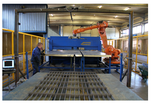
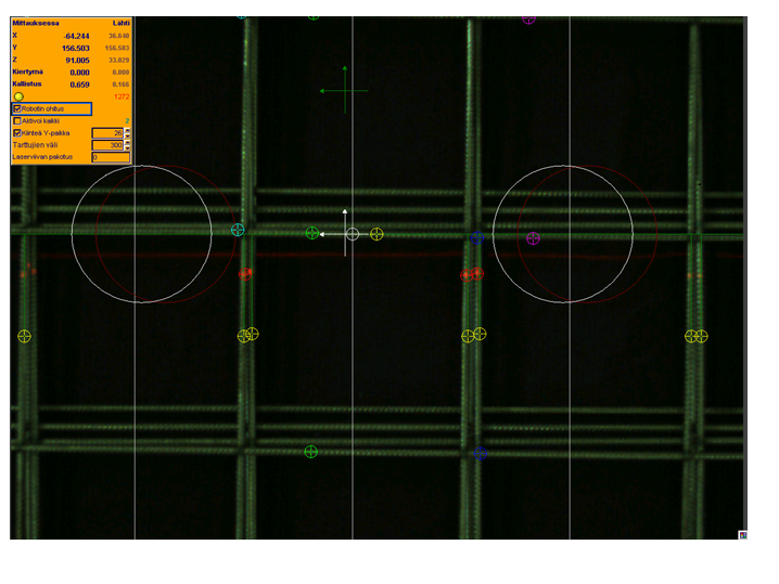
The robot that is reponsible for picking the rebar nets for cutting, needs the following information about the point of picking the nets: x-, y- and z-coordinates, rotation angle and tilt angle of the net. Picking point of the nets should be in the outermost transverse iron but not in the crossing irons welding points. Intersection points should be recognized, so they can be taken into consideration when determining the picking point
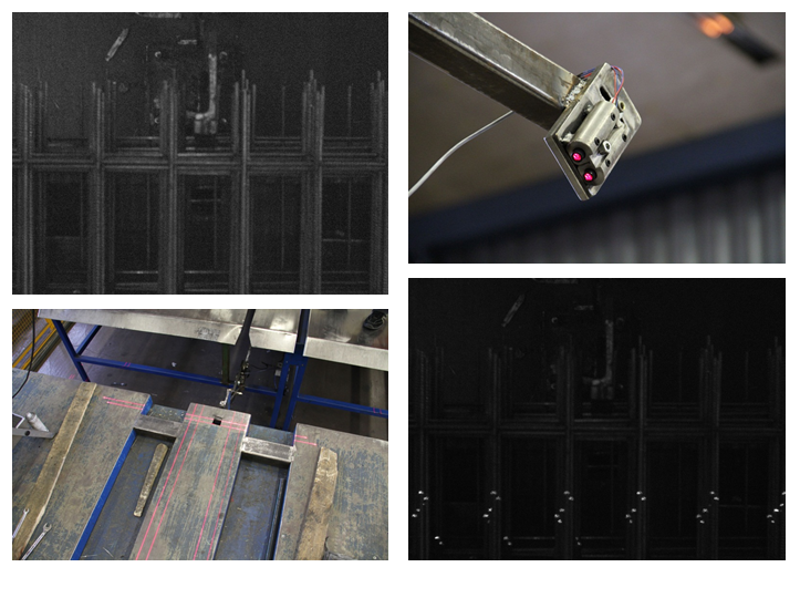
In the final setup, a smart camera and six line lasers were used along with increased height in the camera-, lighting stand.Location and pose of the uppermost net is determined by light dots location, the dots are created by the six laser lines. All of the image analyzing happens inside the camera and the results are sent out to the robot. Robot gets the information of the next net in the queue while it’s still cutting the previous net. Thus the robot can work around the clock, and it doesn’t have to wait for the camera system to calculate the location of the next net to be cutted.